A countermeasure against bottlenecks in the SMT line, the buffers are distinguished into good PCB buffering and NG PCB stacking functions


Reliable 3D Data based Statistical Process Control
3D data based SPI-AOI communication solution


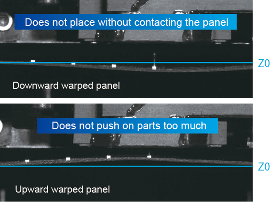
Z-tracking 3D Compensation
The KY8030-2’s moiré technology enables realtime measurement and compensation of board warp, solving the PCB Warp issues with respect to the ideal plane that impact inspection accuracy and reliability.
KY8030-2 adds automated solder paste dispensing as an optional add-on. The high-precision, userfriendly dispensing system helps to eliminate costly mistakes due in large part to insufficient solder in open joints, lean fillets, and weak joints. The KY8030-2’s automatic dispensing option repairs such issues before pass through, resulting in enhanced first pass yield and reduced operational costs.

The KSMART Process Optimizer assists with real-time communication of monitoring data from the screen printing processes including insufficient paste, excessive paste, shape deformity based on 3D volume and shape measurements, as well as instances of no paste, bridging, and placement errors.
Real-time alerts prevent print quality problems and monitor printer hardware engagement and print ready status via Pre-DOE, while automatically optimizing printer parameters. It provides real-time alarms based on printing quality during DOE through PDM Lite and verification of printing
results following application of recommended parameters resulting in significant print quality improvements and increased yield.

Reliable 3D Data based Statistical Process Control
The KY8030-2 also comes with a reliable 3D-Data based Statistical Process Control which lets manufacturers evaluate data using an intuitive graphic interface. It also helps increase the speed of root-cause analysis to provide users with enhanced equipment uptime.
SPC Dashboard Inspection Analysis
3D data based SPI-AOI communication solution
Z-tracking 3D Compensation
The KY8030-3’s moiré technology enables realtime measurement and compensation of board warp, solving the PCB Warp issues with respect to the ideal plane that impact inspection accuracy and
Pad Referencing 2D Compensation
The high-quality IR light provides for automatic for fast and easy reference teaching even without the CAD file. Moreover, the KY8030-3 allows manufacturers to match non-inspection objects (patterns and fiducial marks) on ideal PCB stencil designs with the ideal PCB pad ocations defined by the CAD file in real time with minimum hassle.
KY8030-2 adds automated solder paste dispensing as an optional add-on. The high-precision, userfriendly dispensing system helps to eliminate costly mistakes due in large part to insufficient solder in open joints, lean fillets, and weak joints. The KY8030-2’s automatic dispensing option repairs such issues before pass through, resulting in enhanced first pass yield and reduced operational costs.
The KSMART Process Optimizer assists with real-time communication of monitoring data from the screen printing processes including insufficient paste, excessive paste, shape deformity based on 3D volume and shape measurements, as well as instances of no paste, bridging, and placement errors.
Real-time alerts prevent print quality problems and monitor printer hardware engagement and print ready status via Pre-DOE, while automatically optimizing printer parameters. It provides real-time alarms based on printing quality during DOE through PDM Lite and verification of printing
results following application of recommended parameters resulting in significant print quality improvements and increased yield.
Reliable 3D Data based Statistical Process Control
The KY8030-2 also comes with a reliable 3D-Data based Statistical Process Control which lets manufacturers evaluate data using an intuitive graphic interface. It also helps increase the speed of root-cause analysis to provide users with enhanced equipment uptime.
SPC Dashboard Inspection Analysis
3D data based SPI-AOI communication solution

aSPIre 3 stores and distributes job files and inspection conditions from its centralized DB to multiple SPIs ensuring easy management of modifications and changes following process optimization.
aSPIre 3 has the ability to set up user level groups with various authorities ensuring that the work history of each user is monitored through the user’s data logs.
3D data based SPI-AOI communication solution

aSPIre 3 offers periodical checks on critical items such as 3D/2D light intensity, PZT Feed, Height Accuracy, and XY Offset. It helps operators to take precautionary measures so that SPI can maintain optimal conditions.
aSPIre 3 also minimizes maintenance through auto-verification of machine conditions during operation to reduce process interruptions and enhance equipment uptime.
aSPIre 3 provides analysis of real-time multi-line management data, enabling the comparison of each machine and line, while allowing for management of machine status for all production lines from remote locations.
aSPIre 3 provides a detailed history chart, height, volume, and offset for designated lines by ensuring the best products that yield the available machine ranking. It shows machine stats, model information, yield, and alarm time.

Measurement & Inspection of an Array of Defects
Zenith has the ability to make a clear and concise ‘go-or-no-go’ decision for a solder joint inspection, detecting an array of potential defects including Missing solder, Offset, Rotation, Polarity, Upside down, OCV/OCR, Solder filet, Billboarding, Lifted Lead, Lifted Body, Tombstone, Bridging and more.
Zenith’s intuitive interface makes setup easy, reducing programming time in package registration and setting of inspection conditions. The evaluation benchmark can then be easily managed by an operator, simplifying and speeding up programming, while also making identification universal.

Increases equipment uptime by helping operators perform critical process analyses and optimize default settings from an intuitive graphical interface.
The Library Manager stores inspection conditions and real-time job files in a centralized database and distributes the data to multiple machines.
The Offline Program Optimizer makes program creation, debugging and updates seamless. Allowing operators to automatically deploy modified inspection conditions and fine tune processes starting from the next PCB without altering the production schedule.
Links all inspection results, merging images, trends, charts and inspection results including detailed analysis from the SPI, pre-reflow AOI and post-reflow AOI for total line communication and process analysis.
Job Fine-tuning with Minimum Downtime
The Offline Program Optimizer makes program creation, debugging and updates seamless, allowing operators to automatically deploy modified inspection conditions and fine tune processes starting from the next PCB without stopping the production line or altering the production schedule.
3D data based SPI-AOI communication solution

The optimized, user-friendly graphic interface is simple to use with flexible, custom configurations as well as AI-driven measuring of selected components that proposes recommended inspection conditions from KY Templates built by AOI experts. This allows for simple, seamless and super-fast auto programming that guarantees true-to-life 3D inspection, yielding a 70% reduction in programming time.
KY’s side-view camera solution allows Zenith2 to quickly detect and analyze defects on a wide range of mounted components and chips


Self diagnosis of lighting and calibration ensures an optimal environment & lower TCoO.
Increases equipment uptime by helping operators perform critical process analyses and optimize default settings from an intuitive graphical interface.
The Library Manager stores inspection conditions and real-time job files in a centralized database and distributes the data to multiple machines.
The Offline Program Optimizer makes program creation, debugging and updates seamless. Allowing operators to automatically deploy modified inspection conditions and fine tune processes starting from the next PCB without altering the production schedule.
Links all inspection results, merging images, trends, charts and inspection results including detailed analysis from the SPI, pre-reflow AOI and post-reflow AOI for total line communication and process analysis.
Reliable 3D Data based Statistical Process Control
The KY8030-2 also comes with a reliable 3D-Data based Statistical Process Control which lets manufacturers evaluate data using an intuitive graphic interface. It also helps increase the speed of root-cause analysis to provide users with enhanced equipment uptime.
SPC Dashboard Inspection Analysis
3D data based SPI-AOI communication solution

True 3D Measurement for CNC and Assembly Process
Patented moiré projection technology enables true 3D measurement on CNC / Assembly Process
Micro 3D measurement capability based on Koh Young’s unrivalled accuracry
Monitoring CNC / Assembly Process
Unique measurement inspection for CNC / Assembly Process
Reliable Surface Defect Identification
– Height Repeatability : 20um at 3 sigma on KY calibration taget
– Length Repeatability : 20um at 3 sigma on KY calibration target
– Metrology Capability : Area, Height, Diameter, Volume
– Types of Defects : Scratch, Flaw, Stain, Burr, Missing, Color, Coplanarity and more
Provide Figure & Exterior 3D inspection simutaneously for maximize productivity
Less than 10 min. programming for a complete inspection file with No fine tunning needed


Individual belt operations type
PCB 20 slots (±15mm)
Individual belt operations type
Visual identification of NG PCB
PCB 20 slots (±15mm)
Identifier and RS-232C communications module allow easy identification of NG points (optional)


Accommodates single-size racks
Mode : Loader / Unloader
NG stacking / Buffering
By pass
Individual belt operations type
Fast cycle
Buffering + NG stacking
Accepts one magazine rack
PCB 20 slots (±15mm)

Separates PCB sheets with a blade
Maximum PCB load of 30 kg
Separates PCB sheets with clamping
Maximum PCB load of 50 kg


Fixed vacuum pad
Maximum PCB load of 50 kg
Valve manual lock
Suitable for off-line laser line


Accommodates single-size racks
Accommodates multiple rack sizes


Accommodates multiple rack sizes
Accommodates single rack
Designed for limited spaces
Accommodates multiple rack sizes
Accommodates two magazine racks
Single shuttle integral type
Designed for limited spaces


Accommodates single-size racks
Accommodates multiple rack sizes

Accommodates multiple rack sizes
Accommodates single rack
Designed for limited spaces
Accommodates multiple rack sizes
Accommodates two magazine racks
Single shuttle integral type
Designed for limited spaces


The vacuum soldering process and its advantages

Building a vacuum soldering system

Versions of vacuum systems
The vacuum systems can be individually configured. You can choose between different lengths for the heating zone, the vacuum module and the cooling zone. There is also the choice between one, two or three track versions.
Vacuum S - heating zone length 3.0 m
Zone concept
Fewer zones - fewer fan units - less consumption!
The number of zones has no influence on a good ΔT . The system is aligned according to the process and defined by the heating chamber length - not by the number of zones. A high air volume
is important . SMT achieves this with few but powerful fans.

Process gas cleaning

Cooling concept
The cooling zone length and equipment (heat exchanger plates, optimized air baffles, etc.) can be flexibly selected. The cooling medium is supplied via an integrated cooling unit or an external cooling tower or the domestic water supply.

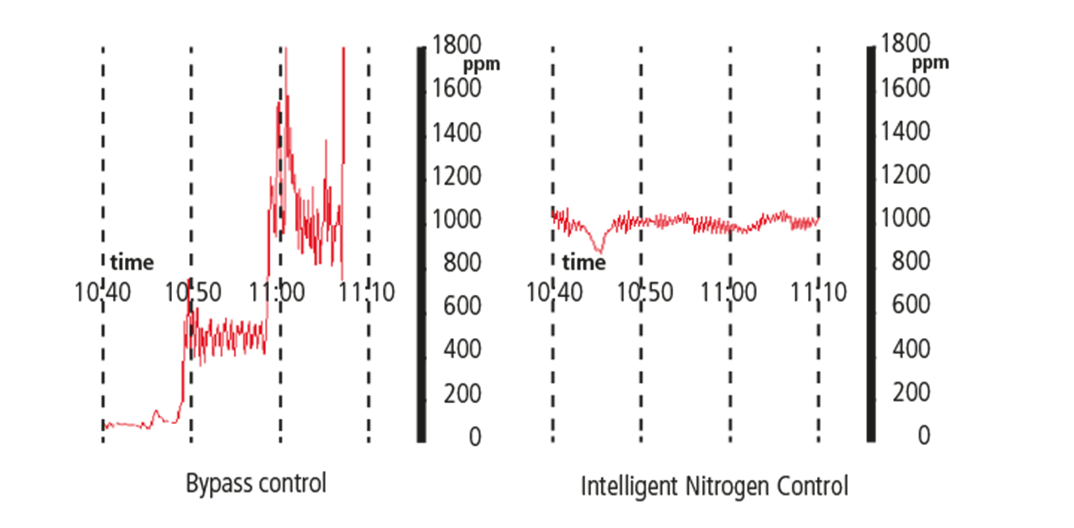
Intelligent nitrogen control
The intelligent nitrogen control with optimal control behavior reduces nitrogen consumption to a minimum. A nitrogen parameter that can be used for traceability is provided.
process
Individual fan control in all zones
Explanations
Our reflow systems can be individuallyconfigured.
R series
•R460 - heating zone length 4.6 m
•R410 - heating zone length 4.1 m
•R360 - heating zone length 3.6 m
•R320 - heating zone length 3.2 m
QP series
•Quattro Peak M - heating zone length 2.6 m
•Quattro Peak S - heating zone length 2.1 m

System features

· Size and weight of the tower varies according tothe size and quantity of themagazines.
· Dimension: 2200 * 1500 * 2150 (L*W*H/mm)
· Weight: 1400kg
· Magazinesize :320 * 355 * 575 (L*W*H/mm)
· Controlby : PC


3DMEASUREMENT FREE FROM SHADOWS AND DIFFUSE REFLECTIONS
•EAGELE 3D 8800 AOI applies 8-wayprojection for 3D measurement to all models to minimize errors due to shadow effects, and performs 100% 2D & 3Dinspection simultaneously in all FOV areas.
•As a result, it is possible tosecure close to perfect detection power while significantly reducing falsecalls.
ACCURATEAND CONVENIENT INSPECTION USING SIDE CAMERA
Real-time inspection is possible by simultaneously using fourhigh-definition cameras and a TOP camera on the side and using a dedicatedalgorithm optimized for side inspection.
•4-Way Side Camera(Option)
•Capable of detecting innerbridges that cannot be seen in the top camera
•Detection possible inside theconnector
•Convenient Teaching usingexisting algorithms
3D measurement/inspection of 27mm high parts
EAGEL 3D AOI provides the option to inspect up to 30mm in height using Pemtron's proprietary technology.


